Binary Trees, Graphs, and Network Knowledge (Week 8) - Learning Objectives
Assessment Structure
- 1 hour, 40 minutes
- Mixture of multiple choice (15-20), free response (1-3) and VSCode (1-3) problems, each with multiple specs.
- Free response just requires enough detail to answer the question, 1-3 sentences. As long as you are able to explain the concept and answer all aspects that it asks, you are good.
- Coding problems will have specs to run (
npm test) and check your work against
- Standard assessment procedures
- You will be in an individual breakout room
- Use a single monitor and share your screen
- Only have open those resources needed to complete the assessment:
- Zoom
- VSCode
- Browser with AAO and Progress Tracker (to ask questions)
- Approved Resources for this assessment:
- MDN: https://developer.mozilla.org/en-US/docs/Web/JavaScript
Binary Trees (W8D2) - Learning Objectives
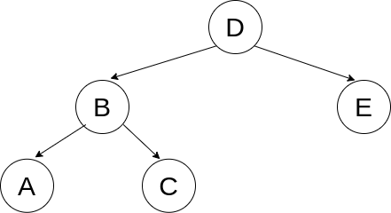
Binary Trees
- Explain and implement a Binary Tree.
- Identify the three types of tree traversals: pre-order, in-order, and post-order.
- Pre-order: Values are accessed as soon as the node is reached.
- In-order: Values are accessed after we have fully explored the left but before we explore the right branch.
- Post-order: Values are accessed after all of our children have been accessed.
- *Breadth First: The previous three are types of Depth First Traversals. Breadth first accesses values of nodes by level, left to right, top to bottom.
- Given a tree, be able to determine the order of each traversal type:
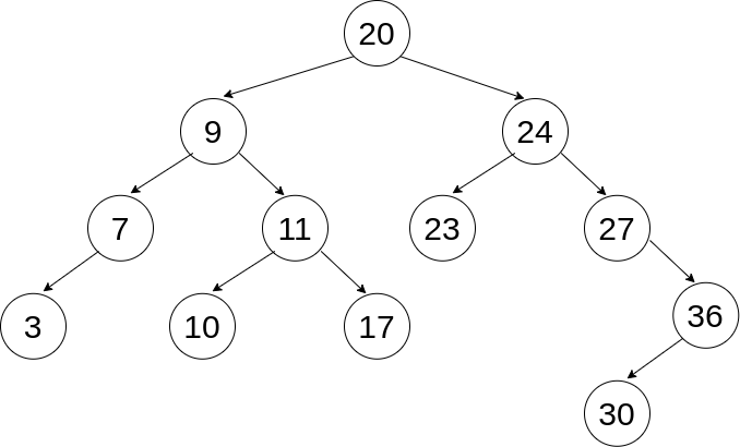
- Breadth First: 20, 9, 24, 7, 11, 23, 27, 3, 10, 17, 36, 30
- Pre-order: 20, 9, 7, 3, 11, 10, 17, 24, 23, 27, 36, 30
- In-order: 3, 7, 9, 10, 11, 17, 20, 23, 24, 27, 30, 36
- Post-order: 3, 7, 10, 17, 11, 9, 23, 30, 36, 27, 24, 20
- Explain and implement a Binary Search Tree.
Graphs (W8D3) - Learning Objectives
Graphs
- Explain and implement a Graph.
- A good place to start with explaining a graph is comparing to a tree:
- A graph can:
- Consist of any collection of nodes and edges (no limits on connections)
- Have cycles
- Have disconnected portions (a forest, with multiple trees, for example)
- Be missing a root node (don’t have to have one node that connects to everything)
- In a tree, we had an idea of children and parents, in a graph we have neighbors (no hierarchy)
- Just like how we could represent trees in multiple ways, we can represent graphs many ways as well, with advantages/disadvantages to each:
- Adjacency Matrix - 2D Array
- Visually clear what’s going on
- One axis (outside array) has an entry (inner array) for each node in the graph. If one node is connected to another node in the graph, our entry in the inner array is set to true. Otherwise the entry is false.
let matrix = [
/*          A       B       C       D       E       F   */
/*A*/    [true,  true,   true,   false,  true,   false],
/*B*/    [false, true,   false,  false,  false,  false],
/*C*/    [false, true,   true,   true,   false,  false],
/*D*/    [false, false,  false,  true,   false,  false],
/*E*/    [true,  false,  false,  false,  true,   false],
/*F*/    [false, false,  false,  false,  true,   true]
];
- Adjacency List - POJO
- Object where every value in the graph has a key
- Value for the key is an array with each other node that it is connected to (neighbors)
- Easy to iterate through
- Doesn’t take up as much space as an Adjacency Matrix or Node
- Can refer to the entire graph by referencing the object
- Nodes
- Similar to our linked list or tree implementations
- Track the value and the neighbors array as instance variables on the node
- We don’t have a reference to the overall graph with this implementation
- Traverse a graph.
- Using a NODE implementation with ITERATION:
- Using an ADJACENCY LIST with RECURSION:
- One advantage of an adjacency list is that, since we have a reference to the whole graph, we can access nodes that aren’t connected to our starting point. This may or may not be desired, so we can implement our functions differently to account for this feature.
- Using an ADJACENCY LIST with ITERATION:
NOTE: The breadth-first solution to the Adjacency List problem to consider can be found from refactoring the above function. How?
- With all of thes implementations, we should be able to make conclusions from these traversals as well instead of just console logging.
- Is it possible to get from node A to node B?
- Here we’re really implementing a search, like the breadthFirstSearch problem.
- What is the maximum/minimum value we can encounter if we start at node X?
- Instead of returning a boolean, we want to compare values of nodes and return the appropriate value
- If we do this recursively we can compare this node and to each of its neighbors values and return the maximum up the call stack.
- If we do this iteratively, we can keep a currentMax variable as we traverse and update it if we find a new max value.
- etc.
Network Knowledge (W8D4) - Learning Objectives
Network Models
NOTE: USE THE ANKI FLASHCARDS TO STUDY FOR THIS PORTION OF THE ASSESSMENT
- Describe the structure and function of network models from the perspective of a developer.
- Recognize a given model as the TCP/IP model

- Give a brief description of each layer (What is its major concern and an example)
- Application: User-facing data, such as HTTP or FTP (file transfer)
- Transport: Connectivity between clients and servers, such as TCP or UDP
- Internet: Routing between separate networks, such as IP
- Link: Low-level communication between local resources on a network, such as Ethernet
- Recognize a given model as the OSI model

- Give a brief description of each layer (What is its major concern and an example)
- Application (Layer 7)
- Example: HTTP
- Information used by client-side software
- Presentation (Layer 6)
- Example: JPEG, GIF
- Data gets translated into a presentable format
- Often called the syntax layer since it translates machine-readable syntax into human-readable syntax
- Session (Layer 5)
- Example: RPC (Remote Procedure Call)
- Authentication and data continuity
- Authorize actions, reestablish session from dropped connections
- Transport (Layer 4)
- Example: TCP, UDP
- Mirrors TCP/IP’s Transport Layer
- Focused on data integrity and connectivity
- Network (Layer 3)
- Example: IP
- Mirrors TCP/IP’s Internet Layer
- Manages connections between different remote networks
- Data Link (Layer 2)
- Example: Ethernet
- Connections between one network interface to another
- Primarily used by machines in a local network (ie targeting different MAC addresses)
- Physical (Layer 1)
- Example: DSL, 802.11 (Wi-Fi)
- Translating from electrical signals to bits of data
IP Suite
- Identify the correct fields of an IPv6 header.
- Compared to IPv4’s 14 (yikes!) header fields, we now only use 8 fields. They are all listed here, but the main things to be familiar with are the version to indicate IPv4 vs IPv6, as well as the source and destination IP address fields:
- Version: Just like IPv4, the first four bits of our packet header represent our version number, which is
0110, representing our decimal 6.
- Traffic Class: Identifies the type of packet data
- Flow Label: Adds packet sequencing to IP, but is experimental
- Payload Length: Specifiies the size of this packet
- Next Header: Typically identifies the Transport Layer protocol (TCP, UDP, etc.). It can also indicate an extension header is present, where extra options for the packet are specified (similar concept to the Options field of IPv4, but a different, chainable implementation)
- Hop Limit: Decremented by one each time this packet passes through an intermediary. Prevents the packet from being passed around forever.
- Source IP Address
- Destination IP Address

- Distinguish an IPv4 packet from an IPv6.
- The easiest way to distinguish between an IPv4 and IPv6 packet is the “Version” field of the header.
- The first four bits of any packet’s header indicate which IP version is being used
- For IPv4, we use the binary
0100 and for IPv6 we use 0110 (4 and 6 respectively in decimal)
- (This is a great opportunity to review binary and hexadecimal notation!)
- In additional to the “Version” field itself, if we know where the header ends, we would also generally be able to tell based on the size.
- IPv6 headers have a fixed length of 320 bits, whereas an IPv4 header will generally be much smaller at 160 bits (plus any optional headers).
- This is obviously not the most reliable, so we should always just refer to those first four bits that indicate the version.
- Describe the following subjects and how they relate to one another: IP Addresses, Domain Names, and DNS.
- An IP address is how we specify a location on the internet. When we send out a request, the IP address in the header is what guides our request to its final destination. Just like an address we would use to signify a unique house, the IP address signifies a unique location on the internet that we want to handle our request.
- A Domain Name is our solution to solving the issue of long, seemingly random numbers being difficult for humans to memorize. They are the friendly name for a website’s host. Instead of having to type in that you want to go to 208.65.153.238, you can just say that you want to go to http://www.youtube.com.
- When we look at a website, such as https://open.appacademy.io/learn/js-py–aug-2020-online/, we can break it down into components:
https:// is the protocol that we are making the request withopen.appacademy.io is the domain. The domain can be composed of any number of subdomains.
- The right-most domain is the top-level domain (TLD), which is maintained by domain registries. Common TLDs would be .com, .org, .gov, etc
- Each preceding domain can be referred to as a second-level, third-level, fourth-level, etc., domain. In our example,
appacademy is the second-level and open is the third-level domain.
- We often combine a second-level and top-level domain to refer to a generic ‘domain’ term, such as
google.com, amazon.com, usa.gov, appacademy.io, etc.
- DNS is the Domain Name System. It’s what allows us to utilize our friendly domain names and have them converted into the IP addresses that we actually intended to connect to.
- Zone files are maintained by name servers that contains host names, IP addresses, and resource types. These files are what allow us to bounce around between servers that know more specifics about our desired resource, ultimately getting to the server that has the exact IP address that our domain name maps to.
- There are multile types of records included in the zone file that we should be familiar with:
- SOA: Start of Authority. Points to a name server that is the primary authority for the domain. This record is present on every name server. For example, if I’m looking for
appacademy.io, the name server will know where more information about io domains is located and send me along in that direction.
- NS: Name Servers. Points to name servers for the zone. There will always be at least two name servers per zone for redundancy.
- A / AAAA: Map a resource directly to an IP address. These are the ultimate records that our queries are looking for.
A records are used for IPv4 addresses and AAAA records are used for IPv6 addresses.
- CNAME: Acts as an alias, indicating what resource this domain should also point to. (We often see this with the www subdomain, where a CNAME record for www would exist for google.com, indicating we can request
www.google.com and get the same response as google.com)
- MX: Mail Exchanger. Used to direct messages to a mail server instead of an IP address (allows us to use
@gmail.com instead of @123.45.67.89 - which is obviously not the actual address)
- Identify use cases for the TCP and UDP protocols.
- Comparing TCP (Transmission Control Protocol) to UDP (User Datagram Protocol):
- TCP:
- A reliable transport protocol. As packets are sent between locations, their integrity is double-checked to ensure nothing was lost.
- A persistent and consistent connection. When a connection is established between two sources, it is maintained until both sides send the signal that the connection will be terminated.
- Use cases: HTTP (for a webpage, ensure we get all parts of the HTML so that the browser can piece it together and parse it, for example), file transfers, media streaming (YouTube), etc.
- UDP:
- Unreliable transport protocol. There is no confirmation that anything that is sent out is received. “Yelling into the void”
- Prioritizes speed! We don’t have to confirm every packet that is sent. We may lose some pieces of data, but we are prioritizing that we are receiving that information in real-time.
- Use cases: real-time communication like live video and VoIP (if we had to confirm every packet of a zoom transmission, we would end up very out of sync, since we would wait on those dropped frames instead of skipping to the live ones coming in), DNS resolution (prioritizing speed here, getting the user to the appropriate URL quickly - they can always refresh if needed)
- Describe the following subjects and how they relate to one another: MAC Address, IP Address, and a port.
- MAC Addresses are associated with a physical device. It stays with the device as an identifier. Even if we connect to a different network, our MAC address stays the same.
- If we ever run into collisions with other devices with the same address, we can alias this to another value, but in general it would never need to change. The chances of a collision are exceedingly rare.
- IP Addresses are how we are referring to a specific location within or across networks. We can have a local address (192.168.0.0 to 192.168.255.255 is a common range to refer to local addresses), which is how we can reference something within our private network, and we can have a public address (something more like 73.41.66.92), which would allow a connection from outside of our local network. The IP address can change, it is not tied directly to a specific machine. It can be mapped to a domain name so that others can reference a user-friendly name such as google.com instead of having to memorize a number.
- Ports are how we can route information to a specific application once we’ve made it to the computer itself. In general, it is a virtual address that we assign that an application is then listening for traffic on. When a request comes in to a specific port, an application (like a server that we create with Express, or our Postgres database - concepts we’ll be exploring soon!) is then able to be given that information directly.
- (Optional) Identify the fields of a TCP segment.
- This is optional additional information! I’ve still included it here since it is listed on the AAO platform, but know that this material is more in depth than you need to know.
- The TCP segment has many different header fields, similar to the fields on an IP packet:

- Source Port: The port that the request originated from
- Destination Port: The port that the request is intended for (determines which socket to use). Our most recognizable example may be when we think about localhost. If we set up a server on port 3000, the packets being sent need a destination port of 3000 for our server to receive them.
- Sequence Number: Extablishes ordering of data. A starting number is created (Initial Sequence Number, or ISN), then each subsequent segment’s number is incremented based on the size of the previous segment.
- Acknowledgement Number: The number that corresponds to the sequence number we are responding to. The acknowledgement number is the sequence number that we received plus the length of the data that was transferred, plus 1. This allows us to determine if we’ve received all of the data. If there is a discrepency in numbers, we have to retransmit data.
- Data Offset: The length of the segment header, allowing us to determine where our options field ends (or if an options field even exists)
- Reserved: 3 bits that are always 0. Available for future flags.
- Control Flags: 9 (currently) bits that are used for congestion monitoring and to indicate the connection lifecycle
- Window Size: Indicates how much data should be sent, allowing for throttling if a receiver is getting overloaded.
- Checksum: Error-checking mechanism for an individual segment
- Urgent Pointer: Marks data as urgent, which will be processed right away. Commonly used to terminate a transfer instead of having to wait until it finishes.
- Options: Similar to packets’ options fields, extra headers that indicate other extra details about the segment.
- (Optional) Describe how a TCP connection is negotiated.
- This is optional additional information! I’ve still included it here since it is listed on the AAO platform, but know that this material is more in depth than you need to know.
- Starting a Connection

- Our first segment header has a synchronize flag, indicating we are opening a connection.
- Our sequence number should be used by the response in their acknowledgement.
- The receiver responds with a synchronize flag of their own as well as an acknowledgement flag.
- The acknowledgement number sent back is the sequence number we are responding to, plus the length of data sent (0), plus 1. This shows the sender that we received their initial request.
- We also send our own sequence number in order to check that the other side of this connection is responding appropriately.
- We send back an acknowledgment based on the sequence number sent by the server.
- After this acknowledgement, both sides now know that a connection is established.
- Dropped Data

- If a segment doesn’t reach the server, there will be a discrepency between the sequence number that it receives and what it expects based on the previous segment.
- The server resends its most recent acknowledgement in order to indicate that we need to resend the segment that comes next in the series.
- This acknowledgement is what makes TCP reliable. If we ever miss data, we know that it has occurred and we can request it to be sent again.
- Closing a Connection

- When we want to indicate that we are done with the transmission, we send a finished flag to the server.
- The server sends an acknowledgement response, then waits a brief period to make sure there are no more segments are coming in.
- The server then sends its own finished flag, indicating that it is closing the connection.
- When we receive the finished flag from the server, we also wait a brief period to make sure we’ve received all segments, then send a final acknowledgment flag. Both sides of the connection are now closed.
- Explaining the difference between network devices like a router and a switch.
- We talked about three main categories of network devices: hubs, switches, and routers.
- A hub is simply taking message and sending it out to everything connected to it. It works on a local network of machines in order to duplicate a message it receives and send it to everything else that connects to it. There is not filtering or directing of messages, it is simply repeating that message to everyone.
- A switch is similar to a hub but has some additional functionality. It is able to look at the MAC address that the message is intended for and send it specifically to the appropriate device (it keeps a MAC address table that maps these addresses to the local IP addresses of the network). If it doesn’t know which IP address it needs to send to specifically, it can also perform the same flooding that a hub can, repeating the message to everyone until it gets a device that it is looking for.
- A router is how we are connecting our local network to other networks, including the internet. It acts as an entry/exit point from the local network to other resources. It implements Network Address Translation (NAT), which assigns the router one IP address for all external communication. The ports associated with incoming requests can then be mapped to the appropriate local network device based on a a routing table that it maintains, similar to the switch’s table.
These will not be on your assessment
- These are tools to be able to see some of the above topics presented on your own machine. Their use, as in commands that you would run or how to read the output, are not assessable material, they are simply included to provide an opportunity to see the some of the above concepts in action.
- Use
traceroute to show routes between your computer and other computers.
- Passing the
traceroute utility a URL or IP address argument will allow us to see the connections that were made in order to get from your machine to its destination.
- For example, when I run
traceroute appacademy.io, I get the following output:
traceroute to appacademy.io (104.28.30.159), 30 hops max, 60 byte packets
 1  _gateway (10.0.0.1)  0.828 ms  0.990 ms  1.163 ms
 2  96.120.14.37 (96.120.14.37)  18.138 ms  26.191 ms  24.144 ms
 3  96.110.159.217 (96.110.159.217)  27.812 ms  27.976 ms  27.969 ms
 4  ae-2-ar01.sacramento.ca.ccal.comcast.net (162.151.18.133)  27.957 ms  27.735 ms  27.472 ms
 5  be-36441-cs04.sunnyvale.ca.ibone.comcast.net (96.110.41.109)  28.062 ms be-36421-cs02.sunnyvale.ca.ibone.comcast.net (96.110.41.101)  29.186 ms be-36431-cs03.sunnyvale.ca.ibone.comcast.net (96.110.41.105)  28.958 ms
 6  * * *
 7  be-301-cr01.9greatoaks.ca.ibone.comcast.net (96.110.37.170)  25.456 ms be-304-cr01.9greatoaks.ca.ibone.comcast.net (96.110.37.182)  25.619 ms be-303-cr01.9greatoaks.ca.ibone.comcast.net (96.110.37.178)  25.428 ms
 8  be-12578-pe04.9greatoaks.ca.ibone.comcast.net (68.86.88.18)  25.207 ms  23.485 ms  25.393 ms
 9  66.208.228.6 (66.208.228.6)  28.015 ms  26.484 ms  26.271 ms
10  104.28.30.159 (104.28.30.159)  23.235 ms  21.448 ms  21.641 ms
- The output shows the number of hops that I have taken, “friendly”/DNS name of the hop if applicable with the IP address in parentheses, and the amount of time it took to get a response from that leg of the route.
- There are three times listed because the
traceroute utility attempts the connection three times in order to get some results to compare.
- If we don’t get a response for any of our attempts, an asterisk (
*) is shown instead of a time.
- One thing to note with this utility is that Windows firewall will generally block the pings that
traceroute attempts to make from a WSL implementation. If on WSL, try using the very similar tracert utility directly within the Windows cmd prompt. This utility is generally not blocked by the Windows firewall.
- There are ways that we can go about allowing specific types of traffic through the firewall to get
traceroute to work as expected from within WSL, but for our purposes I wouldn’t go through the trouble just for this exercise.
- Issue: https://github.com/microsoft/WSL/issues/1930
- Allowing through the firewall (references Vista, but the same concepts still apply to modern Windows): https://www.howtogeek.com/howto/windows-vista/allow-pings-icmp-echo-request-through-your-windows-vista-firewall/
- Use Wireshark to show/inspect network traffic.
- Wireshark is a tool that allows us to inspect any packets that are coming through our network.
- It allows us to see the content of those packets so that we can see things like how the IP header fields are laid out, the Transport protocol used (TCP, UDP, etc.), and the application content.
- Wireshark is often blocked from use on networks because it allow the user to inspect traffic, including other computers that are on the network. It’s used here just to see examples of what doing different activities on our computers looks like in terms of the packets that are sent.